
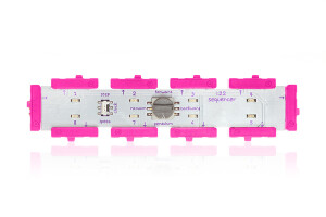

The new Little Bits module allows for connecting up to 8 outputs and control them in sequential patterns.
The Little Bits Sequencer features two clock modes that control when the module transitions from sequence step to sequence step. In “step” mode the sequence transitions to a new sequence step on input low-to-high transitions. In this mode, the clock output is high when the input is above 2.5V, and the clock output is low when the input is below 2.5V.
In “speed” mode the sequence transitions to a new sequence step at a fixed frequency. The step frequency is proportional to the voltage at the input. At 0V input, the frequency is 0Hz (the sequencer does not step). At 5 volts the step frequency is approximately 80Hz. In this mode, the clock output is a square waveform at the step frequency.
The four sequence modes control the order in which the 8 sequenced outputs are activated. At any given time, there is exactly one of the 8 sequenced outputs set to 5V. All other outputs are set to 0V. “Forward” mode sets output 1 to 5V, then on the next step output 2 is set to 5V, and so on. After activating each output in turn, the sequence then continuously repeats, starting at output 1 ; “backwards” mode is the same as “forward” mode, except that the sequence steps from output 8 to output 1 ; “pendulum” mode sets output 1 to 5V, then on the next step output 2 is set to 5V, and so on. Upon reaching output 8, the sequence reverses and steps down from 7 to 1 ; “random” mode sets a randomly selected output to 5V at each step.
The input signal is buffered by an opamp (U1), then passed through a single pole RC low pass filter, then a 2-pole active low pass filter (U3). The combined filters band limit the signal to 160Hz with an 18dB per octave filter slope. This signal is split into two paths. One path leads to the Analog-to-Digital Converter (ADC) of an Atmel ATMEGA168 microcontroller (U2). The other path leads to a General Purpose Input-Output (GPIO) pin on the same microcontroller. The path to the ADC is used in “speed” mode because in speed mode, we need to precisely measure the input voltage, and the ADC is precise. The path to the GPIO pin is used in “step” mode, because we need to quickly measure the timing of an input low-to-high transition, and the GPIO pin responds very quickly to transitions. Depending on the clock mode, microcontroller converts the measured input values into either the sequencer step speed in “speed” mode, or simply goes to the next sequencer step when it detects a low-to-high transition in “step” mode. These values are translated into signals that control the pins of the microcontroller connected to the various outputs.
The Sequencer module is available for $36 at littlebits.cc.


Viewers of this article also read...
-
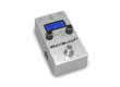 This Summer, jam with BeatBuddy Mini for $99
Singular Sound has announced a special offer on their BeatBuddy Mini personal drum machine.
This Summer, jam with BeatBuddy Mini for $99
Singular Sound has announced a special offer on their BeatBuddy Mini personal drum machine.
-
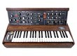 Moogfest: Moog to bring back Minimoog Model D
While Moogfest 2016 is currently (May 19-22) being held in Durham, NC, Moog is bringing back Minimoog Model D through a pop-up factory.
Moogfest: Moog to bring back Minimoog Model D
While Moogfest 2016 is currently (May 19-22) being held in Durham, NC, Moog is bringing back Minimoog Model D through a pop-up factory.
-
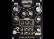 [MUSIKMESSE] Dreadbox present Drips
Dreadbox is at the Musikmesse to present Drips, a Eurorack format modular drum machine.
[MUSIKMESSE] Dreadbox present Drips
Dreadbox is at the Musikmesse to present Drips, a Eurorack format modular drum machine.